 We present here a more detailed and technical explanation of Tesla coil operation compared to the one displayed at the exhibit.
We present here a more detailed and technical explanation of Tesla coil operation compared to the one displayed at the exhibit.
A Tesla coil uses an air-core transformer to step the voltage up to a very high value, which in our exhibit is about 500,000 Volts. It operates at high frequency which is generated by an electrical oscillator. In our case the frequency is increased from the line frequency of 60 hertz (cycles per second) to about 90,000 hertz using a spark gap oscillator. 60 hertz is the standard frequency that is used for alternating current (AC) electric power the USA. Tesla coils often have a large metal object in the shape of a ball or a donut at the top from which electric discharges are produced. Our Tesla coil is located inside of a large Faraday cage made of wire mesh. This is not required for the operation of the coil, but serves to protect the visitors from the electrical discharge as well as from strong electric and magnetic fields that are generated and also to prevent noisy radio waves from being transmitted and causing interference.
In Tesla coils which are powered by standard AC power, there is normally a preliminary stage in which the voltage is raised substantially using an iron-core transformer. In our Tesla coil, a neon sign transformer steps the voltage up to 15,000 Volts from the line voltage of 120 Volts. This transformer has a primary winding and a secondary winding. Think of the core as a closed path of iron, with the two windings wrapped around it.
![]() The AC voltage applied to the primary winding causes an oscillating magnetic field to build up in the iron core that circulates around through both windings. This field in turn induces a voltage in the secondary winding. In this type of transformer, the output of the secondary has a voltage that is primarily determined by the ratio of turns in the secondary to that in the primary. Given a turns ratio of 125, the 120 volts AC applied to the primary results in 15,000 volts on the secondary. More details about transformers can be found in most physics books on electricity and magnetism.
The AC voltage applied to the primary winding causes an oscillating magnetic field to build up in the iron core that circulates around through both windings. This field in turn induces a voltage in the secondary winding. In this type of transformer, the output of the secondary has a voltage that is primarily determined by the ratio of turns in the secondary to that in the primary. Given a turns ratio of 125, the 120 volts AC applied to the primary results in 15,000 volts on the secondary. More details about transformers can be found in most physics books on electricity and magnetism.
The Tesla coil itself is also a transformer, however it does not have an iron core. Iron tends to intensify the magnetic field, but is not very useful at the high frequency used by the Tesla coil. In our coil, the primary is a large flat spiral made of copper tubing which has about 17 turns and is 3 feet in diameter.
 It is located at the base of the tall secondary winding under the white plastic disc. The number of turns that are in use can be adjusted with a movable clip in order to tune the Tesla coil (currently set to use about 12 turns). The secondary has about 1088 turns and is wound with fine copper "magnet" wire. Magnet wire is electrically insulated with a thin, often transparent, coating and is typically used to make transformers or electromagnets. The copper color of the secondary is due to the winding; the wire is too small to see the individual turns in the photo. The primary and secondary coils are each part of resonant circuits that can sustain oscillations at about 90,000 Hz. This electrical resonance is similar in many respects to a mechanical resonance like the ringing of a bell, or the vibrations of a guitar string. Coils of wire such as the primary and secondary of the Tesla coil have a property known as inductance which is related to the magnetic field produced by current in the coil. Resonance is achieved with the addition of a capacitor into each circuit. Knowing the capacitance and inductance allows one to calculate the resonant frequency. In the primary, the effective capacitance is generated by a series and parallel combination of 39 individual capacitors (the capacitor bank). These capacitors are the white tubular components that are visible in the lower section of the Tesla coil. In the secondary, the capacitance is primarily generated by the large donut shaped "toroid" on top of the tall coil, plus some contribution from the coil itself. In a capacitor, a voltage applied between two conductors causes electric charge to accumulate on them.
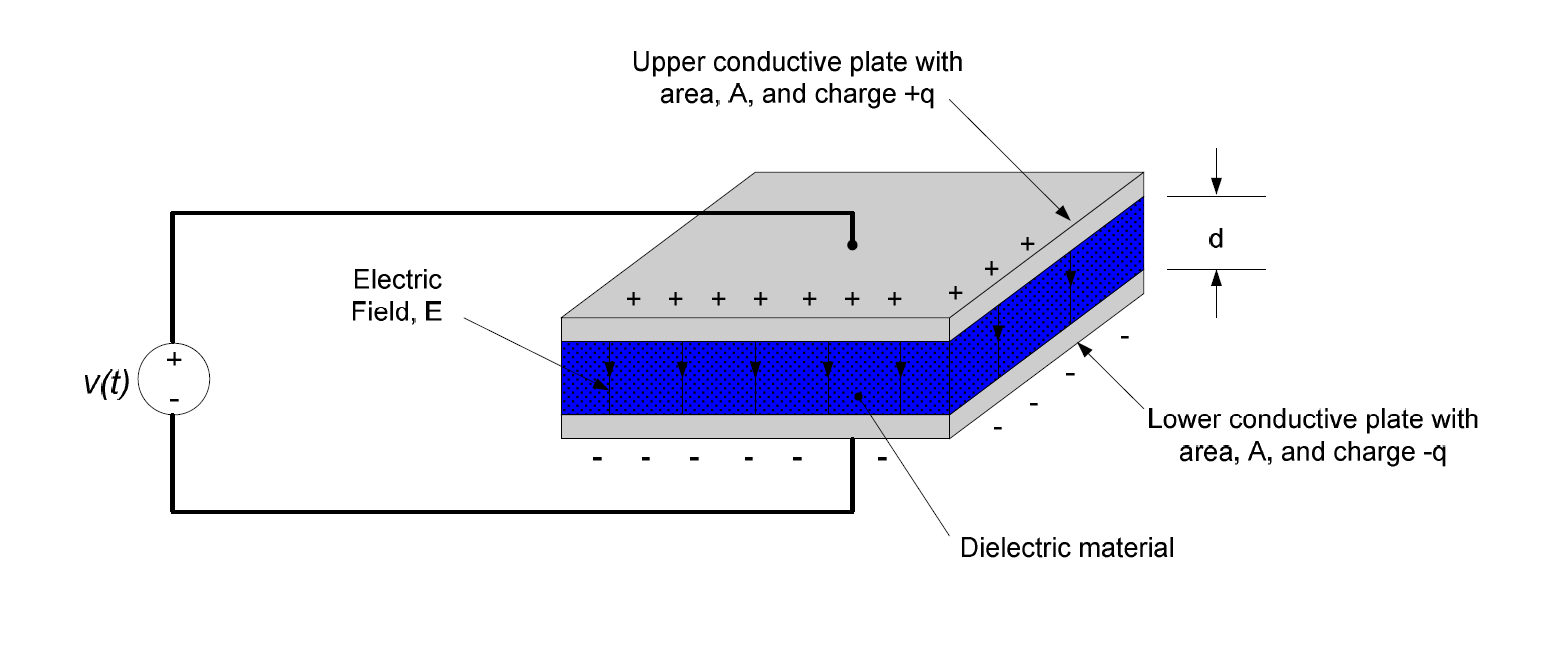 In tubular capacitors, the conductors are long strips of metal foil separated by a thin nonconducting dielectric. This is rolled up to make it more compact. For the secondary circuit, the capacitance is between the toroid and the Faraday cage. If the cage wasn't present, it would be between the toroid and the ground plane. These resonant circuits also store energy which oscillates back and forth between magnetic energy in the coils and electric energy in the capacitors. The energy stored in the toroid is released when the discharge occurs and a "lightning bolt" propagates outwards from the toroid towards the Faraday cage.
There is also a spark gap in the primary circuit. This is formed by two metal electrodes with their ends facing each other and with a gap in between them.
 A fan blows air through the gap which provides cooling and also replaces ionized air with fresh air between successive firings of the gap. In the photo, the gap is not firing and the fan is behind it. During operation, the bright light you see coming from the lower part of the Tesla coil is caused by the spark gap. The spark is kept out of direct sight because it is extremely bright and it is harmful to stare at it. It also makes more noise that the discharge from the toroid. The voltage from the transformer is applied to the electrodes and the gap fires when this voltage exceeds the breakdown voltage of the air in the gap causing the air to become ionized. Once it fires, the air remains ionized for a fraction of a second, and forms a highly conducting path that allows the primary circuit to resonate at 90,000 Hertz at very high current and voltage. Since the secondary is resonant at about the same frequency, its voltage increases with each cycle until the electric field in the air adjacent to the surface of the toroid exceeds the breakdown field of the air. At this point a lightning-like discharge begins on the toroid and propagates outwards through the air towards the Faraday Cage. If the voltage on the toroid fails to reach this value, no discharge will occur. Once the discharge begins, the voltage will tend to level off and then decline as the charge on the toroid propagates outwards along the discharge path. In our Tesla coil we estimate that the output voltage peaks at about 500,000 Volts.
Fleet Tesla Coil simplified schematic

The breakdown field for air is about 3 million volts per meter. Since the distance between the toroid and the Faraday cage is about 1.2 meters, it is tempting to assume that the breakdown would occur at about 3.6 million volts, but this is not the case. This is because surface of the toroid is curved, and this causes the electric field strength near its surface to be much greater than elsewhere inside the cage. In fact, when the size of the cage is large compared to the size of the toroid, the breakdown voltage is primarily determined by the size of the toroid alone, depending only slightly on the distance to the cage. For our toroid alone, a calculation yields 501 kV. A correction for the effect of the cage brings this down to 424 kV. It is reasonable to assume that to produce a robust discharge the voltage must rise past this by some amount. We therefore estimate the output at 500 kV. Direct measurement of this voltage is difficult or impossible, but it can be estimated using calculations based on other measurements such as the nearby electric field strength or the current flowing into the base of the tall secondary coil. A larger toroid with a larger radius of curvature will have a proportionately higher breakdown voltage, but will require more powerful circuitry in order to reach that voltage and produce a discharge.
The lower end of the tall secondary coil is often connected to an earth ground that is separate from the building electrical ground. This is often referred to as the RF ground (RF stands for radio frequency). This reduces any tendency of the high frequency Tesla oscillations being transmitted on the building electrical wiring. However, when a Faraday cage is used, it is connected to the bottom of the coil and the RF fields and currents are largely confined to the inside of the cage. The Faraday cage at Fleet is connected to the building electrical ground for safety purposes.
Neon sign transformers are designed to have an output series inductance whose purpose is to limit the output current when used to power a neon sign. This inductance is often close to resonance with the capacitor bank at 60 Hertz. As a result the output voltage of the neon sign transformer may tend to rise significantly above its rated voltage. This resonance can be helpful in producing a stronger output from the Tesla coil, but it can also increase the electrical stress on the components, possibly causing them to fail. This effect can be reduced, if necessary, by shortening the spark-gap as this will limit the voltage rise to the firing voltage of the gap. The capacitors in the Fleet Tesla coil are mounted on ceramic tile to minimize damage if they burn out. They are bypassed with high resistance "bleeder resistors" whose purpose is to prevent any slow charge build up and also to discharge the capacitors when the Tesla coil is turned off. There is a "safety-gap" across the output of the neon sign transformer. It normally doesn't fire, but is there to protect the transformer from potentially damaging voltage spikes. The components in the diagram labeled "power resistors" are there for a similar purpose.
The built in inductance of the neon sign transformer (mentioned above) may cause the Tesla Coil as a whole to present an inductive load to the electric power system and exhibit a "power factor" causing it to be inefficient. This can be corrected, if desired, by placing an appropriate capacitance in parallel with the input to the neon sign transformer (this component not shown in the simplified schematic).
If one or more metal spikes or rods are added to the toroid as "breakout points" then the discharges will originate from them. Somewhat counterintuitively, this will bring down the output voltage, but may also facilitate sparking or even increase spark length. This is because the electric field strength near the point is greater than near the toroid because of its smaller radius of curvature.
The primary circuit of a large Tesla coil can be extremely hazardous when active because of the high current and high voltage. This includes the neon sign transformer output, the spark gap, spiral coil and capacitor bank. The tall secondary and the output discharges are also hazardous, but somewhat less so because of the relatively high frequency and low current.